DIY Adjustable Bench Power Supply: How to Build One Using a Laptop Charger and XL4015 Module
Every electronics workbench and maker space needs a reliable DC power supply for prototyping, testing LEDs, charging batteries, and troubleshooting microcontrollers. While commercial lab bench supplies are functional, building your own using recycled components is cost-effective, compact, and a rewarding engineering project.
In this guide, we break down how to build a compact, current- and voltage-adjustable lab power supply powered by an ordinary 19V laptop charger, an XL4015 step-down (buck) converter, and a standard dual-display digital panel meter.
Why Use an XL4015 & Laptop Adapter?
- Consistent Power Source: Standard laptop bricks deliver around 19V–20V at 3A–4.7A with built-in short-circuit and thermal protections.
- Independent Voltage & Current Control: The XL4015 module features two onboard multi-turn potentiometers, allowing you to regulate output voltage (down to ~1.25V) and configure constant-current (CC) limiting.
- Compact Footprint: Unlike bulky linear transformers, this switch-mode setup fits neatly into a custom 3D-printed desktop enclosure.
Bill of Materials (BOM)
| Component | Specification / Details |
| Power Source | 19V DC Laptop Power Adapter (3.5A – 4.7A) |
| Buck Converter | XL4015 Constant Voltage / Constant Current (CV/CC) Step-Down Module |
| Display Panel | DSN-VC288 Dual LED Voltmeter & Ammeter (0–100V, 10A) |
| Potentiometers | I used build in potentiometers which comes with XL4015 board |
| Output Terminals | Multiple Battery Connectors |
| Enclosure | Custom 3D-Printed Desktop Case (PETG) |
| DC Input Jack | 5.5×2.5mm Female DC Barrel Jack |
Complete Wiring Schematic
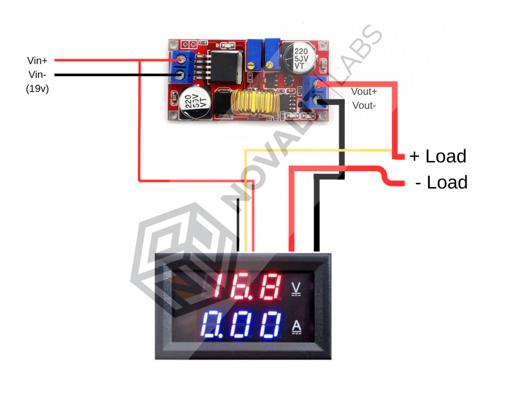
Step-by-Step Wiring Guide
Wiring a dual-display meter can be tricky because the ground paths must be isolated correctly so that current passes through the internal shunt resistor:
- Powering the Display Panel (Thin Red & Black Wires):
- Connect the thin red wire to the laptop adapter 19V positive rail (+).
- Connect the thin black wire to the laptop adapter ground rail (-).
- Pro-Tip: Powering the meter directly from the input voltage ensures the LED screen stays lit even when you adjust the output voltage down to 0V/1.25V.
- Voltage Sensing (Yellow Wire):
- Connect the yellow sensing wire directly to the XL4015 OUT (+) terminal. This allows the voltmeter to accurately display the regulated output voltage going to your load.
- Current Measurement / Shunt (Thick Wires):
- Connect the thick black wire to the XL4015 OUT (-) terminal.
- Connect the thick red wire to the Front Panel Negative (-) Output Terminal.
- Note: The load’s return current flows through the front panel negative terminal, into the meter’s internal shunt via the thick red wire, and exits via the thick black wire back to the regulator ground.
- Positive Output:
- Connect the XL4015 OUT (+) directly to the Front Panel Positive (+) Output Terminal.
- Front Panel Potentiometers (Optional but Recommended):
- Desolder the tiny onboard multi-turn trimpots on the XL4015 board.
- Run extension wires to panel-mount potentiometers installed on the 3D-printed front plate for smooth, ergonomic manual tuning.
Calibration & First Power-Up
- Before connecting a sensitive load, power on the unit with your laptop brick.
- Use a dedicated digital multimeter to verify the output voltage at the output jacks.
- Fine-tune the small calibration trimpots located on the back of the DSN-VC288 display panel until the displayed voltage matches your multimeter.
- Test the current limiting feature using a power resistor or an LED module.
Conclusion & Next Steps
With a clean wiring layout and a sturdy 3D-printed enclosure, this setup transforms an obsolete laptop charger into an indispensable piece of lab gear.
Stay tuned to the Novalit Labs engineering blog for the upcoming 3D printable STL enclosure files and front-plate CAD templates!